
Schematic diagram of the flow battery solar container model
As the photovoltaic (PV) industry continues to evolve, advancements in Schematic diagram of the flow battery solar container model have become critical to optimizing the utilization of renewable energy sources. From innovative battery technologies to intelligent energy management systems, these solutions are transforming the way we store and distribute solar-generated electricity.
6 FAQs about [Schematic diagram of the flow battery solar container model]
How do solar panels and battery modules work?The solar panels and battery module use the same inverter and share the grid intercon-nection, reducing the cost of equipment. This also reduces power losses from inverting the current and running separate interconnection lines to the grid, as the solar array and battery are dispatched as a single facility.
How do solar panels connect to a battery?Solar panels can be coupled, or linked, to a battery either through alternating current (AC) cou-pling or direct current (DC) coupling. AC current flows rapidly on electricity grids both forward and backward. DC current, on the other hand, flows only in one direction.
What are redox flow batteries?Specifically, redox flow batteries represent one type of grid-scale energy storage device with long life spans of at least 10 years and capabilities like peak shaving and load leveling.
How does a solar system work?1. AC Coupled BESS. In AC-coupled systems, there are separate inverters for the solar panels and the battery. Both the solar panels and the battery module can be discharged at full power and they can either be dispatched together or independently, creating flexibility in how the system operates.
How pvdesign is a battery storage solution?In pvDesign, we assume that the storage solution is modular. The user has to set the energy of a battery container. Alternatively, the energy of a single battery rack and the number of racks to include per container can be set. BatCont is the energy of the battery container. [Wh]
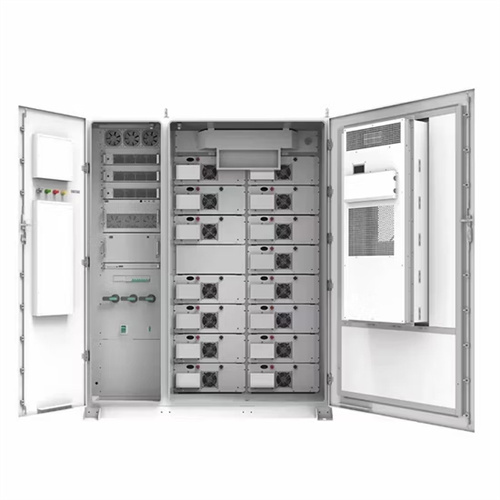
What is the capacity of the battery container?Including1. 6300*2438*2896mm, internal cable of battery container. The total capacity of the battery container is 5.016MWh, which integrates the battery system, BMS, fire suppression system, chiller, and environmental monitoring in the container, compatible with the 2h system and 4h system.
Related Contents
-
Schematic diagram of the flow battery solar container model
-
Schematic diagram of the principle of liquid flow battery solar container technology
-
Schematic diagram of vanadium liquid flow battery solar container system
-
Schematic diagram of solar container battery absorbing lithium
-
Schematic diagram of the solar container battery principle of integrated equipment
-
Schematic diagram of solar container industrial battery
List of relevant information about Schematic diagram of the flow battery solar container model
Schematic diagram of the flow battery energy storage model
Schematic diagram of the flow battery energy storage model Flow batteries: Design and operation. A flow battery contains two substances that undergo electrochemical reactions in which electrons are
Utility-scale battery energy storage system (BESS)
Utility-scale BESS system description — Figure 2. Main circuit of a BESS Battery storage systems are emerging as one of the potential solutions to increase power system flexibility in the presence of
Flow battery energy storage principle diagram
Up until now, most studies within the flow battery community have largely focused on the all-aqueous flow battery systems using metallic ions, particularly the widely studied and developed all-vanadium
Schematic diagram of a typical stationary battery energy storage
Download scientific diagram | Schematic diagram of a typical stationary battery energy storage system (BESS). Greyed-out sub-components and applications are beyond the scope of this work. from
Working principle diagram of vanadium electric solar container battery
Schematic diagram of the principle of liquid flow battery The principle of operation in flow batteries involves the circulation of electrolyte solutions from external reservoirs into a cell containing a
1MW Battery Energy Storage System
Utilizing Tier 1 280Ah LFP battery cells, each BESS is designed for a install friendly plug-and-play commissioning. Each system is constructed in a environmentally controlled container including fire
Battery Design Module Application Library
Introduction Redox flow batteries store the energy in the liquid electrolytes, pumped through the cell and stored in external tanks, rather than in the porous electrodes as for conventional batteries. This
Rechargeable redox flow batteries: Flow fields, stacks and design
batteries with flow field designs through both computational modeling and experimental approaches. The late Joseph M. Prahl (recently passed away) was a full Professor in the Department of Mechanical
Contact Integrated Localized Bess Provider
Enter your inquiry details, We will reply you in 24 hours.
The solar panels and battery module use the same inverter and share the grid intercon-nection, reducing the cost of equipment. This also reduces power losses from inverting the current and running separate interconnection lines to the grid, as the solar array and battery are dispatched as a single facility.
How do solar panels connect to a battery?Solar panels can be coupled, or linked, to a battery either through alternating current (AC) cou-pling or direct current (DC) coupling. AC current flows rapidly on electricity grids both forward and backward. DC current, on the other hand, flows only in one direction.
What are redox flow batteries?Specifically, redox flow batteries represent one type of grid-scale energy storage device with long life spans of at least 10 years and capabilities like peak shaving and load leveling.
How does a solar system work?1. AC Coupled BESS. In AC-coupled systems, there are separate inverters for the solar panels and the battery. Both the solar panels and the battery module can be discharged at full power and they can either be dispatched together or independently, creating flexibility in how the system operates.
How pvdesign is a battery storage solution?In pvDesign, we assume that the storage solution is modular. The user has to set the energy of a battery container. Alternatively, the energy of a single battery rack and the number of racks to include per container can be set. BatCont is the energy of the battery container. [Wh]
What is the capacity of the battery container?Including1. 6300*2438*2896mm, internal cable of battery container. The total capacity of the battery container is 5.016MWh, which integrates the battery system, BMS, fire suppression system, chiller, and environmental monitoring in the container, compatible with the 2h system and 4h system.
Related Contents
-
Schematic diagram of the flow battery solar container model
-
Schematic diagram of the principle of liquid flow battery solar container technology
-
Schematic diagram of vanadium liquid flow battery solar container system
-
Schematic diagram of solar container battery absorbing lithium
-
Schematic diagram of the solar container battery principle of integrated equipment
-
Schematic diagram of solar container industrial battery
List of relevant information about Schematic diagram of the flow battery solar container model
Schematic diagram of the flow battery energy storage model
Schematic diagram of the flow battery energy storage model Flow batteries: Design and operation. A flow battery contains two substances that undergo electrochemical reactions in which electrons are
Utility-scale battery energy storage system (BESS)
Utility-scale BESS system description — Figure 2. Main circuit of a BESS Battery storage systems are emerging as one of the potential solutions to increase power system flexibility in the presence of
Flow battery energy storage principle diagram
Up until now, most studies within the flow battery community have largely focused on the all-aqueous flow battery systems using metallic ions, particularly the widely studied and developed all-vanadium
Schematic diagram of a typical stationary battery energy storage
Download scientific diagram | Schematic diagram of a typical stationary battery energy storage system (BESS). Greyed-out sub-components and applications are beyond the scope of this work. from
Working principle diagram of vanadium electric solar container battery
Schematic diagram of the principle of liquid flow battery The principle of operation in flow batteries involves the circulation of electrolyte solutions from external reservoirs into a cell containing a
1MW Battery Energy Storage System
Utilizing Tier 1 280Ah LFP battery cells, each BESS is designed for a install friendly plug-and-play commissioning. Each system is constructed in a environmentally controlled container including fire
Battery Design Module Application Library
Introduction Redox flow batteries store the energy in the liquid electrolytes, pumped through the cell and stored in external tanks, rather than in the porous electrodes as for conventional batteries. This
Rechargeable redox flow batteries: Flow fields, stacks and design
batteries with flow field designs through both computational modeling and experimental approaches. The late Joseph M. Prahl (recently passed away) was a full Professor in the Department of Mechanical
Contact Integrated Localized Bess Provider
Enter your inquiry details, We will reply you in 24 hours.
Solar panels can be coupled, or linked, to a battery either through alternating current (AC) cou-pling or direct current (DC) coupling. AC current flows rapidly on electricity grids both forward and backward. DC current, on the other hand, flows only in one direction.
What are redox flow batteries?Specifically, redox flow batteries represent one type of grid-scale energy storage device with long life spans of at least 10 years and capabilities like peak shaving and load leveling.
How does a solar system work?1. AC Coupled BESS. In AC-coupled systems, there are separate inverters for the solar panels and the battery. Both the solar panels and the battery module can be discharged at full power and they can either be dispatched together or independently, creating flexibility in how the system operates.
How pvdesign is a battery storage solution?In pvDesign, we assume that the storage solution is modular. The user has to set the energy of a battery container. Alternatively, the energy of a single battery rack and the number of racks to include per container can be set. BatCont is the energy of the battery container. [Wh]
What is the capacity of the battery container?Including1. 6300*2438*2896mm, internal cable of battery container. The total capacity of the battery container is 5.016MWh, which integrates the battery system, BMS, fire suppression system, chiller, and environmental monitoring in the container, compatible with the 2h system and 4h system.
Related Contents
-
Schematic diagram of the flow battery solar container model
-
Schematic diagram of the principle of liquid flow battery solar container technology
-
Schematic diagram of vanadium liquid flow battery solar container system
-
Schematic diagram of solar container battery absorbing lithium
-
Schematic diagram of the solar container battery principle of integrated equipment
-
Schematic diagram of solar container industrial battery
List of relevant information about Schematic diagram of the flow battery solar container model
Schematic diagram of the flow battery energy storage model
Schematic diagram of the flow battery energy storage model Flow batteries: Design and operation. A flow battery contains two substances that undergo electrochemical reactions in which electrons are
Utility-scale battery energy storage system (BESS)
Utility-scale BESS system description — Figure 2. Main circuit of a BESS Battery storage systems are emerging as one of the potential solutions to increase power system flexibility in the presence of
Flow battery energy storage principle diagram
Up until now, most studies within the flow battery community have largely focused on the all-aqueous flow battery systems using metallic ions, particularly the widely studied and developed all-vanadium
Schematic diagram of a typical stationary battery energy storage
Download scientific diagram | Schematic diagram of a typical stationary battery energy storage system (BESS). Greyed-out sub-components and applications are beyond the scope of this work. from
Working principle diagram of vanadium electric solar container battery
Schematic diagram of the principle of liquid flow battery The principle of operation in flow batteries involves the circulation of electrolyte solutions from external reservoirs into a cell containing a
1MW Battery Energy Storage System
Utilizing Tier 1 280Ah LFP battery cells, each BESS is designed for a install friendly plug-and-play commissioning. Each system is constructed in a environmentally controlled container including fire
Battery Design Module Application Library
Introduction Redox flow batteries store the energy in the liquid electrolytes, pumped through the cell and stored in external tanks, rather than in the porous electrodes as for conventional batteries. This
Rechargeable redox flow batteries: Flow fields, stacks and design
batteries with flow field designs through both computational modeling and experimental approaches. The late Joseph M. Prahl (recently passed away) was a full Professor in the Department of Mechanical
Contact Integrated Localized Bess Provider
Enter your inquiry details, We will reply you in 24 hours.
Specifically, redox flow batteries represent one type of grid-scale energy storage device with long life spans of at least 10 years and capabilities like peak shaving and load leveling.
How does a solar system work?1. AC Coupled BESS. In AC-coupled systems, there are separate inverters for the solar panels and the battery. Both the solar panels and the battery module can be discharged at full power and they can either be dispatched together or independently, creating flexibility in how the system operates.
How pvdesign is a battery storage solution?In pvDesign, we assume that the storage solution is modular. The user has to set the energy of a battery container. Alternatively, the energy of a single battery rack and the number of racks to include per container can be set. BatCont is the energy of the battery container. [Wh]
What is the capacity of the battery container?Including1. 6300*2438*2896mm, internal cable of battery container. The total capacity of the battery container is 5.016MWh, which integrates the battery system, BMS, fire suppression system, chiller, and environmental monitoring in the container, compatible with the 2h system and 4h system.
Related Contents
-
Schematic diagram of the flow battery solar container model
-
Schematic diagram of the principle of liquid flow battery solar container technology
-
Schematic diagram of vanadium liquid flow battery solar container system
-
Schematic diagram of solar container battery absorbing lithium
-
Schematic diagram of the solar container battery principle of integrated equipment
-
Schematic diagram of solar container industrial battery
List of relevant information about Schematic diagram of the flow battery solar container model
Schematic diagram of the flow battery energy storage model
Schematic diagram of the flow battery energy storage model Flow batteries: Design and operation. A flow battery contains two substances that undergo electrochemical reactions in which electrons are
Utility-scale battery energy storage system (BESS)
Utility-scale BESS system description — Figure 2. Main circuit of a BESS Battery storage systems are emerging as one of the potential solutions to increase power system flexibility in the presence of
Flow battery energy storage principle diagram
Up until now, most studies within the flow battery community have largely focused on the all-aqueous flow battery systems using metallic ions, particularly the widely studied and developed all-vanadium
Schematic diagram of a typical stationary battery energy storage
Download scientific diagram | Schematic diagram of a typical stationary battery energy storage system (BESS). Greyed-out sub-components and applications are beyond the scope of this work. from
Working principle diagram of vanadium electric solar container battery
Schematic diagram of the principle of liquid flow battery The principle of operation in flow batteries involves the circulation of electrolyte solutions from external reservoirs into a cell containing a
1MW Battery Energy Storage System
Utilizing Tier 1 280Ah LFP battery cells, each BESS is designed for a install friendly plug-and-play commissioning. Each system is constructed in a environmentally controlled container including fire
Battery Design Module Application Library
Introduction Redox flow batteries store the energy in the liquid electrolytes, pumped through the cell and stored in external tanks, rather than in the porous electrodes as for conventional batteries. This
Rechargeable redox flow batteries: Flow fields, stacks and design
batteries with flow field designs through both computational modeling and experimental approaches. The late Joseph M. Prahl (recently passed away) was a full Professor in the Department of Mechanical
1. AC Coupled BESS. In AC-coupled systems, there are separate inverters for the solar panels and the battery. Both the solar panels and the battery module can be discharged at full power and they can either be dispatched together or independently, creating flexibility in how the system operates.
How pvdesign is a battery storage solution?In pvDesign, we assume that the storage solution is modular. The user has to set the energy of a battery container. Alternatively, the energy of a single battery rack and the number of racks to include per container can be set. BatCont is the energy of the battery container. [Wh]
What is the capacity of the battery container?Including1. 6300*2438*2896mm, internal cable of battery container. The total capacity of the battery container is 5.016MWh, which integrates the battery system, BMS, fire suppression system, chiller, and environmental monitoring in the container, compatible with the 2h system and 4h system.
Related Contents
-
Schematic diagram of the flow battery solar container model
-
Schematic diagram of the principle of liquid flow battery solar container technology
-
Schematic diagram of vanadium liquid flow battery solar container system
-
Schematic diagram of solar container battery absorbing lithium
-
Schematic diagram of the solar container battery principle of integrated equipment
-
Schematic diagram of solar container industrial battery
List of relevant information about Schematic diagram of the flow battery solar container model
Schematic diagram of the flow battery energy storage model
Schematic diagram of the flow battery energy storage model Flow batteries: Design and operation. A flow battery contains two substances that undergo electrochemical reactions in which electrons are
Utility-scale battery energy storage system (BESS)
Utility-scale BESS system description — Figure 2. Main circuit of a BESS Battery storage systems are emerging as one of the potential solutions to increase power system flexibility in the presence of
Flow battery energy storage principle diagram
Up until now, most studies within the flow battery community have largely focused on the all-aqueous flow battery systems using metallic ions, particularly the widely studied and developed all-vanadium
Schematic diagram of a typical stationary battery energy storage
Download scientific diagram | Schematic diagram of a typical stationary battery energy storage system (BESS). Greyed-out sub-components and applications are beyond the scope of this work. from
Working principle diagram of vanadium electric solar container battery
Schematic diagram of the principle of liquid flow battery The principle of operation in flow batteries involves the circulation of electrolyte solutions from external reservoirs into a cell containing a
1MW Battery Energy Storage System
Utilizing Tier 1 280Ah LFP battery cells, each BESS is designed for a install friendly plug-and-play commissioning. Each system is constructed in a environmentally controlled container including fire
Battery Design Module Application Library
Introduction Redox flow batteries store the energy in the liquid electrolytes, pumped through the cell and stored in external tanks, rather than in the porous electrodes as for conventional batteries. This
Rechargeable redox flow batteries: Flow fields, stacks and design
batteries with flow field designs through both computational modeling and experimental approaches. The late Joseph M. Prahl (recently passed away) was a full Professor in the Department of Mechanical
In pvDesign, we assume that the storage solution is modular. The user has to set the energy of a battery container. Alternatively, the energy of a single battery rack and the number of racks to include per container can be set. BatCont is the energy of the battery container. [Wh]
What is the capacity of the battery container?Including1. 6300*2438*2896mm, internal cable of battery container. The total capacity of the battery container is 5.016MWh, which integrates the battery system, BMS, fire suppression system, chiller, and environmental monitoring in the container, compatible with the 2h system and 4h system.
Related Contents
-
Schematic diagram of the flow battery solar container model
-
Schematic diagram of the principle of liquid flow battery solar container technology
-
Schematic diagram of vanadium liquid flow battery solar container system
-
Schematic diagram of solar container battery absorbing lithium
-
Schematic diagram of the solar container battery principle of integrated equipment
-
Schematic diagram of solar container industrial battery
Including1. 6300*2438*2896mm, internal cable of battery container. The total capacity of the battery container is 5.016MWh, which integrates the battery system, BMS, fire suppression system, chiller, and environmental monitoring in the container, compatible with the 2h system and 4h system.
List of relevant information about Schematic diagram of the flow battery solar container model
Schematic diagram of the flow battery energy storage model
Schematic diagram of the flow battery energy storage model Flow batteries: Design and operation. A flow battery contains two substances that undergo electrochemical reactions in which electrons are
Utility-scale battery energy storage system (BESS)
Utility-scale BESS system description — Figure 2. Main circuit of a BESS Battery storage systems are emerging as one of the potential solutions to increase power system flexibility in the presence of
Flow battery energy storage principle diagram
Up until now, most studies within the flow battery community have largely focused on the all-aqueous flow battery systems using metallic ions, particularly the widely studied and developed all-vanadium
Schematic diagram of a typical stationary battery energy storage
Download scientific diagram | Schematic diagram of a typical stationary battery energy storage system (BESS). Greyed-out sub-components and applications are beyond the scope of this work. from
Working principle diagram of vanadium electric solar container battery
Schematic diagram of the principle of liquid flow battery The principle of operation in flow batteries involves the circulation of electrolyte solutions from external reservoirs into a cell containing a
1MW Battery Energy Storage System
Utilizing Tier 1 280Ah LFP battery cells, each BESS is designed for a install friendly plug-and-play commissioning. Each system is constructed in a environmentally controlled container including fire
Battery Design Module Application Library
Introduction Redox flow batteries store the energy in the liquid electrolytes, pumped through the cell and stored in external tanks, rather than in the porous electrodes as for conventional batteries. This
Rechargeable redox flow batteries: Flow fields, stacks and design
batteries with flow field designs through both computational modeling and experimental approaches. The late Joseph M. Prahl (recently passed away) was a full Professor in the Department of Mechanical
Contact Integrated Localized Bess Provider
Enter your inquiry details, We will reply you in 24 hours.