
Standard marking of drawings of mechanical solar container devices
IEC 60617 contains graphical symbols for use in electrotechnical diagrams. All the parts (Ed. 2 or 3) of the previously published IEC 60617 have been incorporated into this database that currently includes some 1900 symbols. The database is the official source of IEC 60617.
As the photovoltaic (PV) industry continues to evolve, advancements in Standard marking of drawings of mechanical solar container devices have become critical to optimizing the utilization of renewable energy sources. From innovative battery technologies to intelligent energy management systems, these solutions are transforming the way we store and distribute solar-generated electricity.
4 FAQs about [Standard marking of drawings of mechanical solar container devices]
What is a drawing standard?1RevisionE 10ScopeThese Drawing Standards regulate dimensioning, tolerancing and labelling of technical documents as well as t e symbols to be used.This guideline shall apply for all new parts as well as all applications and departments of HWA AG as we
How do I read and understand engineering fluid diagrams and prints?To read and understand engineering fluid diagrams and prints, usually referred to as P&IDs, an individual must be familiar with the basic symbols. IDENTIFY the symbols used on engineering P&IDs for educators and ejectors. e. Instrument signal (electrical) f. Instrument capillary g. Electrical d. Inert gas
What is a technical drawing standard?The standard begins with a summary of general rules for the execution and structure of technical drawings. It then describes basic conventions for lines, views, cuts and sections, and different types of engineering drawings—including mechanical, architectural, civil, and shipbuilding.
What is a pictorial diagram of a system?pictorial diagram shows the physical arrangement of the elements in a system. The components are outline drawings that show the external shape of each item. Pictorial drawings do not show the internal function of the elements and are not especially valuable for maintenance or troubleshooting. Figure 30 shows a pictorial diagram of a system.
Related Contents
-
Mechanical and electronic solar container module drawings
-
Requirements for marking solar container equipment installation drawings
-
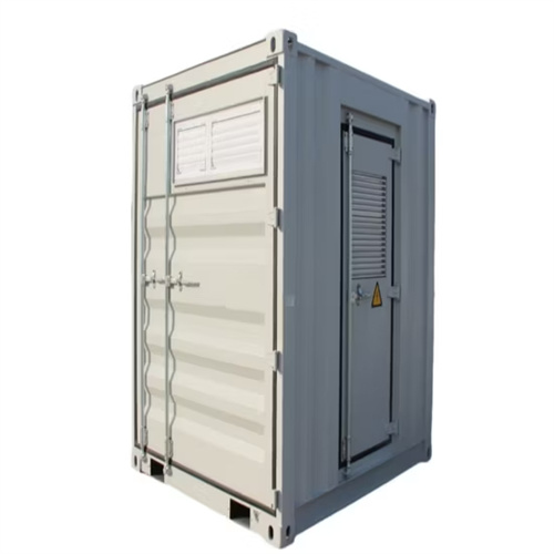
Photos of small mechanical solar container devices
-
Mechanical equipment solar container devices include
-
Meaning of icons of small mechanical solar container devices
-
What are the characteristics of portable solar container devices
List of relevant information about Standard marking of drawings of mechanical solar container devices
Solar Cold Rooms Technical Handbook
container, disperse and fill it up. Since gases are compress-ible, they can be pumped into high pressure containers to compres their volume for storage purposes. In any case, the gas molecules will always
SPECIFICATION FOR PACKAGING, MARKING AND SHIPPING (CD
In addition to this Specification, Suppliers must ensure that Goods delivered comply with, and meet all specific requirements set out in the Contract, Purchase Order and/or Blanket Release, as well as
Building Information Modelling (BIM) Guide for Building Services
Building Information Modelling – Asset Management (BIM-AM) Standards and Guidelines issued by Electrical and Mechanical Services Department (EMSD); BIM Guide for Facilities Upkeep issued by
Mastering the Art of Vertical Packing for Photovoltaic Panels: A
Record Procedures: Document a "how-to" procedure with rack layout drawings and fastener torque specification for every fastener. Mastery of vertical packaging creates each shipment
ASHRAE STANDARD Graphic Symbols for Heating, Ventilating, Air
ASHRAE STANDARD Graphic Symbols for Heating, Ventilating, Air-Conditioning, and Refrigerating Systems Approved by the ASHRAE Standards Committee on February 9, 2005; by the ASHRAE
MECHANICAL STANDARDIZATION OF SEMICONDUCTOR DEVICES
The purpose of this Part of the standard is to extend the recommended practices for the preparation of drawings for semiconductor devices given in AS 379, Part 1, in order to provide general rules for the
Standard: Marking of Parts | PDF
The document outlines the standard for marking parts within the Atlas Copco Group, emphasizing the importance of traceability for product liability and manufacturing accountability. It details the policies
Graphical symbols for diagrams – TC 3
This publication provides conventions, helpful when applying IEC 60617 to symbols for catalogues of real devices, and shows preferable choices where alternative techniques are provided in the standard.
Contact Integrated Localized Bess Provider
Enter your inquiry details, We will reply you in 24 hours.
1RevisionE 10ScopeThese Drawing Standards regulate dimensioning, tolerancing and labelling of technical documents as well as t e symbols to be used.This guideline shall apply for all new parts as well as all applications and departments of HWA AG as we
How do I read and understand engineering fluid diagrams and prints?To read and understand engineering fluid diagrams and prints, usually referred to as P&IDs, an individual must be familiar with the basic symbols. IDENTIFY the symbols used on engineering P&IDs for educators and ejectors. e. Instrument signal (electrical) f. Instrument capillary g. Electrical d. Inert gas
What is a technical drawing standard?The standard begins with a summary of general rules for the execution and structure of technical drawings. It then describes basic conventions for lines, views, cuts and sections, and different types of engineering drawings—including mechanical, architectural, civil, and shipbuilding.
What is a pictorial diagram of a system?pictorial diagram shows the physical arrangement of the elements in a system. The components are outline drawings that show the external shape of each item. Pictorial drawings do not show the internal function of the elements and are not especially valuable for maintenance or troubleshooting. Figure 30 shows a pictorial diagram of a system.
Related Contents
-
Mechanical and electronic solar container module drawings
-
Requirements for marking solar container equipment installation drawings
-
Photos of small mechanical solar container devices
-
Mechanical equipment solar container devices include
-
Meaning of icons of small mechanical solar container devices
-
What are the characteristics of portable solar container devices
List of relevant information about Standard marking of drawings of mechanical solar container devices
Solar Cold Rooms Technical Handbook
container, disperse and fill it up. Since gases are compress-ible, they can be pumped into high pressure containers to compres their volume for storage purposes. In any case, the gas molecules will always
SPECIFICATION FOR PACKAGING, MARKING AND SHIPPING (CD
In addition to this Specification, Suppliers must ensure that Goods delivered comply with, and meet all specific requirements set out in the Contract, Purchase Order and/or Blanket Release, as well as
Building Information Modelling (BIM) Guide for Building Services
Building Information Modelling – Asset Management (BIM-AM) Standards and Guidelines issued by Electrical and Mechanical Services Department (EMSD); BIM Guide for Facilities Upkeep issued by
Mastering the Art of Vertical Packing for Photovoltaic Panels: A
Record Procedures: Document a "how-to" procedure with rack layout drawings and fastener torque specification for every fastener. Mastery of vertical packaging creates each shipment
ASHRAE STANDARD Graphic Symbols for Heating, Ventilating, Air
ASHRAE STANDARD Graphic Symbols for Heating, Ventilating, Air-Conditioning, and Refrigerating Systems Approved by the ASHRAE Standards Committee on February 9, 2005; by the ASHRAE
MECHANICAL STANDARDIZATION OF SEMICONDUCTOR DEVICES
The purpose of this Part of the standard is to extend the recommended practices for the preparation of drawings for semiconductor devices given in AS 379, Part 1, in order to provide general rules for the
Standard: Marking of Parts | PDF
The document outlines the standard for marking parts within the Atlas Copco Group, emphasizing the importance of traceability for product liability and manufacturing accountability. It details the policies
Graphical symbols for diagrams – TC 3
This publication provides conventions, helpful when applying IEC 60617 to symbols for catalogues of real devices, and shows preferable choices where alternative techniques are provided in the standard.
To read and understand engineering fluid diagrams and prints, usually referred to as P&IDs, an individual must be familiar with the basic symbols. IDENTIFY the symbols used on engineering P&IDs for educators and ejectors. e. Instrument signal (electrical) f. Instrument capillary g. Electrical d. Inert gas
What is a technical drawing standard?The standard begins with a summary of general rules for the execution and structure of technical drawings. It then describes basic conventions for lines, views, cuts and sections, and different types of engineering drawings—including mechanical, architectural, civil, and shipbuilding.
What is a pictorial diagram of a system?pictorial diagram shows the physical arrangement of the elements in a system. The components are outline drawings that show the external shape of each item. Pictorial drawings do not show the internal function of the elements and are not especially valuable for maintenance or troubleshooting. Figure 30 shows a pictorial diagram of a system.
Related Contents
-
Mechanical and electronic solar container module drawings
-
Requirements for marking solar container equipment installation drawings
-
Photos of small mechanical solar container devices
-
Mechanical equipment solar container devices include
-
Meaning of icons of small mechanical solar container devices
-
What are the characteristics of portable solar container devices
List of relevant information about Standard marking of drawings of mechanical solar container devices
Solar Cold Rooms Technical Handbook
container, disperse and fill it up. Since gases are compress-ible, they can be pumped into high pressure containers to compres their volume for storage purposes. In any case, the gas molecules will always
SPECIFICATION FOR PACKAGING, MARKING AND SHIPPING (CD
In addition to this Specification, Suppliers must ensure that Goods delivered comply with, and meet all specific requirements set out in the Contract, Purchase Order and/or Blanket Release, as well as
Building Information Modelling (BIM) Guide for Building Services
Building Information Modelling – Asset Management (BIM-AM) Standards and Guidelines issued by Electrical and Mechanical Services Department (EMSD); BIM Guide for Facilities Upkeep issued by
Mastering the Art of Vertical Packing for Photovoltaic Panels: A
Record Procedures: Document a "how-to" procedure with rack layout drawings and fastener torque specification for every fastener. Mastery of vertical packaging creates each shipment
ASHRAE STANDARD Graphic Symbols for Heating, Ventilating, Air
ASHRAE STANDARD Graphic Symbols for Heating, Ventilating, Air-Conditioning, and Refrigerating Systems Approved by the ASHRAE Standards Committee on February 9, 2005; by the ASHRAE
MECHANICAL STANDARDIZATION OF SEMICONDUCTOR DEVICES
The purpose of this Part of the standard is to extend the recommended practices for the preparation of drawings for semiconductor devices given in AS 379, Part 1, in order to provide general rules for the
Standard: Marking of Parts | PDF
The document outlines the standard for marking parts within the Atlas Copco Group, emphasizing the importance of traceability for product liability and manufacturing accountability. It details the policies
Graphical symbols for diagrams – TC 3
This publication provides conventions, helpful when applying IEC 60617 to symbols for catalogues of real devices, and shows preferable choices where alternative techniques are provided in the standard.
The standard begins with a summary of general rules for the execution and structure of technical drawings. It then describes basic conventions for lines, views, cuts and sections, and different types of engineering drawings—including mechanical, architectural, civil, and shipbuilding.
What is a pictorial diagram of a system?pictorial diagram shows the physical arrangement of the elements in a system. The components are outline drawings that show the external shape of each item. Pictorial drawings do not show the internal function of the elements and are not especially valuable for maintenance or troubleshooting. Figure 30 shows a pictorial diagram of a system.
Related Contents
-
Mechanical and electronic solar container module drawings
-
Requirements for marking solar container equipment installation drawings
-
Photos of small mechanical solar container devices
-
Mechanical equipment solar container devices include
-
Meaning of icons of small mechanical solar container devices
-
What are the characteristics of portable solar container devices
pictorial diagram shows the physical arrangement of the elements in a system. The components are outline drawings that show the external shape of each item. Pictorial drawings do not show the internal function of the elements and are not especially valuable for maintenance or troubleshooting. Figure 30 shows a pictorial diagram of a system.
List of relevant information about Standard marking of drawings of mechanical solar container devices
Solar Cold Rooms Technical Handbook
container, disperse and fill it up. Since gases are compress-ible, they can be pumped into high pressure containers to compres their volume for storage purposes. In any case, the gas molecules will always
SPECIFICATION FOR PACKAGING, MARKING AND SHIPPING (CD
In addition to this Specification, Suppliers must ensure that Goods delivered comply with, and meet all specific requirements set out in the Contract, Purchase Order and/or Blanket Release, as well as
Building Information Modelling (BIM) Guide for Building Services
Building Information Modelling – Asset Management (BIM-AM) Standards and Guidelines issued by Electrical and Mechanical Services Department (EMSD); BIM Guide for Facilities Upkeep issued by
Mastering the Art of Vertical Packing for Photovoltaic Panels: A
Record Procedures: Document a "how-to" procedure with rack layout drawings and fastener torque specification for every fastener. Mastery of vertical packaging creates each shipment
ASHRAE STANDARD Graphic Symbols for Heating, Ventilating, Air
ASHRAE STANDARD Graphic Symbols for Heating, Ventilating, Air-Conditioning, and Refrigerating Systems Approved by the ASHRAE Standards Committee on February 9, 2005; by the ASHRAE
MECHANICAL STANDARDIZATION OF SEMICONDUCTOR DEVICES
The purpose of this Part of the standard is to extend the recommended practices for the preparation of drawings for semiconductor devices given in AS 379, Part 1, in order to provide general rules for the
Standard: Marking of Parts | PDF
The document outlines the standard for marking parts within the Atlas Copco Group, emphasizing the importance of traceability for product liability and manufacturing accountability. It details the policies
Graphical symbols for diagrams – TC 3
This publication provides conventions, helpful when applying IEC 60617 to symbols for catalogues of real devices, and shows preferable choices where alternative techniques are provided in the standard.
Contact Integrated Localized Bess Provider
Enter your inquiry details, We will reply you in 24 hours.