
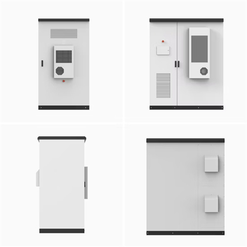
Micro solar container device structure diagram
View the TI TIDM-SOLARUINV reference design block diagram, schematic, bill of materials (BOM), description, features and design files and start designing.
As the photovoltaic (PV) industry continues to evolve, advancements in Micro solar container device structure diagram have become critical to optimizing the utilization of renewable energy sources. From innovative battery technologies to intelligent energy management systems, these solutions are transforming the way we store and distribute solar-generated electricity.
6 FAQs about [Micro solar container device structure diagram]
What is Micro solar inverter block diagram?Figure 1. Micro Solar Inverter Block Diagram This design has a topology that is an interleaved flyback plus SCR full-bridge for industrial frequency inverting. This design has a topology of interleaved flyback with active-clamp plus SCR full-bridge for power converter, and only uses one MCU to realize all of its control.
What is a micro inverter schematic diagram?A micro inverter schematic diagram is a visual representation of the components that make up a micro inverter, which is used in solar panel systems to convert direct current (DC) electricity generated by the solar panels into alternating current (AC) electricity that can be used to power household appliances and other electrical devices.
What ICs can be used for a solar micro inverter?Discover ST's solutions and ICs for your solar micro inverter design, including power MOSFET, SiC diodes, energy metering ICs and connectivity solutions, such as PLC modems.
Can a solar microinverter connect to a PV module?This microinverter has been designed to connect to any PV module having a power rating of approxi-mately 250 watts, with an input voltage range of 25 VDC to 45 VDC, and a maximum open circuit voltage of ~55V. block diagram of the grid-connected Solar Microinverter Reference Design is shown in Figure 5.
What is a solar micro inverter?Solar micro inverters are an emerging segment of the solar power industry. Rather than linking every solar panel in an installation to a central inverter, solar micro inverter-based installations link smaller, or “micro,” inverters individually to each solar panel.
What is a 215W solar microinverter reference design?System designs can be standardized (hardware and software) to improve reliability and reduce costs This Application Note presents and discusses Microchip’s 215W Solar Microinverter Reference Design in detail. The Solar Microinverter Reference Design is a single stage, grid-connected, solar PV microinverter.
Related Contents
-
Structure diagram of the clockwork solar container device
-
Micro solar container device installation diagram
-
Working principle diagram of nitrogen bottle solar container device
-
3d structure diagram of solar container cabinet
-
Solar container monitoring device diagram
-
Detailed explanation of the structure diagram of solar container inverter
List of relevant information about Micro solar container device structure diagram
Grid-Connected Micro Solar Inverter Implement Using a C2000 MCU
This paper describes how to use a TMS320F2802x to design a micro solar inverter with low cost and high performance. Also discussed is the use of the interleaved active-clamp flyback, plus an SCR full
SolaraBox Solar Containers | Products & Configurations
SolaraBox solar containers enable customers to achieve greater energy independence and reduce carbon emissions. By delivering clean, accessible electricity, we support sustainable communities
Grid-Connected Solar Microinverter Reference Design
The Solar Microinverter Reference Design is a single stage, grid-connected, solar PV microinverter. This means that the DC power from the solar panel is converted directly to a rectified
Solar Cold Rooms Technical Handbook
container, disperse and fill it up. Since gases are compress-ible, they can be pumped into high pressure containers to compres their volume for storage purposes. In any case, the gas molecules will always
9. Band diagrams of perovskite solar cells with the device structure
a) Band energy details for each device component before equilibrium, and b) band diagram of the components in equilibrium: the Fermi level is aligned and cliffs are drawn between conduction and
Overview of Solar Steam Devices from Materials and Structures
Various solar vapor devices have been recently developed for freshwater harvesting. Nevertheless, there are relatively few review studies on photothermal conversion materials and the overall structure
Power Topology Considerations for Solar String Inverters and Energy
Figure 2-1 shows the typical architecture of a solar string inverter. Figure 2-1. Solar String Inverter Block Diagram. As Figure 2-1 illustrates, there are three major power blocks in the string inverter.
Contact Integrated Localized Bess Provider
Enter your inquiry details, We will reply you in 24 hours.
Figure 1. Micro Solar Inverter Block Diagram This design has a topology that is an interleaved flyback plus SCR full-bridge for industrial frequency inverting. This design has a topology of interleaved flyback with active-clamp plus SCR full-bridge for power converter, and only uses one MCU to realize all of its control.
What is a micro inverter schematic diagram?A micro inverter schematic diagram is a visual representation of the components that make up a micro inverter, which is used in solar panel systems to convert direct current (DC) electricity generated by the solar panels into alternating current (AC) electricity that can be used to power household appliances and other electrical devices.
What ICs can be used for a solar micro inverter?Discover ST's solutions and ICs for your solar micro inverter design, including power MOSFET, SiC diodes, energy metering ICs and connectivity solutions, such as PLC modems.
Can a solar microinverter connect to a PV module?This microinverter has been designed to connect to any PV module having a power rating of approxi-mately 250 watts, with an input voltage range of 25 VDC to 45 VDC, and a maximum open circuit voltage of ~55V. block diagram of the grid-connected Solar Microinverter Reference Design is shown in Figure 5.
What is a solar micro inverter?Solar micro inverters are an emerging segment of the solar power industry. Rather than linking every solar panel in an installation to a central inverter, solar micro inverter-based installations link smaller, or “micro,” inverters individually to each solar panel.
What is a 215W solar microinverter reference design?System designs can be standardized (hardware and software) to improve reliability and reduce costs This Application Note presents and discusses Microchip’s 215W Solar Microinverter Reference Design in detail. The Solar Microinverter Reference Design is a single stage, grid-connected, solar PV microinverter.
Related Contents
-
Structure diagram of the clockwork solar container device
-
Micro solar container device installation diagram
-
Working principle diagram of nitrogen bottle solar container device
-
3d structure diagram of solar container cabinet
-
Solar container monitoring device diagram
-
Detailed explanation of the structure diagram of solar container inverter
List of relevant information about Micro solar container device structure diagram
Grid-Connected Micro Solar Inverter Implement Using a C2000 MCU
This paper describes how to use a TMS320F2802x to design a micro solar inverter with low cost and high performance. Also discussed is the use of the interleaved active-clamp flyback, plus an SCR full
SolaraBox Solar Containers | Products & Configurations
SolaraBox solar containers enable customers to achieve greater energy independence and reduce carbon emissions. By delivering clean, accessible electricity, we support sustainable communities
Grid-Connected Solar Microinverter Reference Design
The Solar Microinverter Reference Design is a single stage, grid-connected, solar PV microinverter. This means that the DC power from the solar panel is converted directly to a rectified
Solar Cold Rooms Technical Handbook
container, disperse and fill it up. Since gases are compress-ible, they can be pumped into high pressure containers to compres their volume for storage purposes. In any case, the gas molecules will always
9. Band diagrams of perovskite solar cells with the device structure
a) Band energy details for each device component before equilibrium, and b) band diagram of the components in equilibrium: the Fermi level is aligned and cliffs are drawn between conduction and
Overview of Solar Steam Devices from Materials and Structures
Various solar vapor devices have been recently developed for freshwater harvesting. Nevertheless, there are relatively few review studies on photothermal conversion materials and the overall structure
Power Topology Considerations for Solar String Inverters and Energy
Figure 2-1 shows the typical architecture of a solar string inverter. Figure 2-1. Solar String Inverter Block Diagram. As Figure 2-1 illustrates, there are three major power blocks in the string inverter.
Contact Integrated Localized Bess Provider
Enter your inquiry details, We will reply you in 24 hours.
A micro inverter schematic diagram is a visual representation of the components that make up a micro inverter, which is used in solar panel systems to convert direct current (DC) electricity generated by the solar panels into alternating current (AC) electricity that can be used to power household appliances and other electrical devices.
What ICs can be used for a solar micro inverter?Discover ST's solutions and ICs for your solar micro inverter design, including power MOSFET, SiC diodes, energy metering ICs and connectivity solutions, such as PLC modems.
Can a solar microinverter connect to a PV module?This microinverter has been designed to connect to any PV module having a power rating of approxi-mately 250 watts, with an input voltage range of 25 VDC to 45 VDC, and a maximum open circuit voltage of ~55V. block diagram of the grid-connected Solar Microinverter Reference Design is shown in Figure 5.
What is a solar micro inverter?Solar micro inverters are an emerging segment of the solar power industry. Rather than linking every solar panel in an installation to a central inverter, solar micro inverter-based installations link smaller, or “micro,” inverters individually to each solar panel.
What is a 215W solar microinverter reference design?System designs can be standardized (hardware and software) to improve reliability and reduce costs This Application Note presents and discusses Microchip’s 215W Solar Microinverter Reference Design in detail. The Solar Microinverter Reference Design is a single stage, grid-connected, solar PV microinverter.
Related Contents
-
Structure diagram of the clockwork solar container device
-
Micro solar container device installation diagram
-
Working principle diagram of nitrogen bottle solar container device
-
3d structure diagram of solar container cabinet
-
Solar container monitoring device diagram
-
Detailed explanation of the structure diagram of solar container inverter
List of relevant information about Micro solar container device structure diagram
Grid-Connected Micro Solar Inverter Implement Using a C2000 MCU
This paper describes how to use a TMS320F2802x to design a micro solar inverter with low cost and high performance. Also discussed is the use of the interleaved active-clamp flyback, plus an SCR full
SolaraBox Solar Containers | Products & Configurations
SolaraBox solar containers enable customers to achieve greater energy independence and reduce carbon emissions. By delivering clean, accessible electricity, we support sustainable communities
Grid-Connected Solar Microinverter Reference Design
The Solar Microinverter Reference Design is a single stage, grid-connected, solar PV microinverter. This means that the DC power from the solar panel is converted directly to a rectified
Solar Cold Rooms Technical Handbook
container, disperse and fill it up. Since gases are compress-ible, they can be pumped into high pressure containers to compres their volume for storage purposes. In any case, the gas molecules will always
9. Band diagrams of perovskite solar cells with the device structure
a) Band energy details for each device component before equilibrium, and b) band diagram of the components in equilibrium: the Fermi level is aligned and cliffs are drawn between conduction and
Overview of Solar Steam Devices from Materials and Structures
Various solar vapor devices have been recently developed for freshwater harvesting. Nevertheless, there are relatively few review studies on photothermal conversion materials and the overall structure
Power Topology Considerations for Solar String Inverters and Energy
Figure 2-1 shows the typical architecture of a solar string inverter. Figure 2-1. Solar String Inverter Block Diagram. As Figure 2-1 illustrates, there are three major power blocks in the string inverter.
Contact Integrated Localized Bess Provider
Enter your inquiry details, We will reply you in 24 hours.
Discover ST's solutions and ICs for your solar micro inverter design, including power MOSFET, SiC diodes, energy metering ICs and connectivity solutions, such as PLC modems.
Can a solar microinverter connect to a PV module?This microinverter has been designed to connect to any PV module having a power rating of approxi-mately 250 watts, with an input voltage range of 25 VDC to 45 VDC, and a maximum open circuit voltage of ~55V. block diagram of the grid-connected Solar Microinverter Reference Design is shown in Figure 5.
What is a solar micro inverter?Solar micro inverters are an emerging segment of the solar power industry. Rather than linking every solar panel in an installation to a central inverter, solar micro inverter-based installations link smaller, or “micro,” inverters individually to each solar panel.
What is a 215W solar microinverter reference design?System designs can be standardized (hardware and software) to improve reliability and reduce costs This Application Note presents and discusses Microchip’s 215W Solar Microinverter Reference Design in detail. The Solar Microinverter Reference Design is a single stage, grid-connected, solar PV microinverter.
Related Contents
-
Structure diagram of the clockwork solar container device
-
Micro solar container device installation diagram
-
Working principle diagram of nitrogen bottle solar container device
-
3d structure diagram of solar container cabinet
-
Solar container monitoring device diagram
-
Detailed explanation of the structure diagram of solar container inverter
List of relevant information about Micro solar container device structure diagram
Grid-Connected Micro Solar Inverter Implement Using a C2000 MCU
This paper describes how to use a TMS320F2802x to design a micro solar inverter with low cost and high performance. Also discussed is the use of the interleaved active-clamp flyback, plus an SCR full
SolaraBox Solar Containers | Products & Configurations
SolaraBox solar containers enable customers to achieve greater energy independence and reduce carbon emissions. By delivering clean, accessible electricity, we support sustainable communities
Grid-Connected Solar Microinverter Reference Design
The Solar Microinverter Reference Design is a single stage, grid-connected, solar PV microinverter. This means that the DC power from the solar panel is converted directly to a rectified
Solar Cold Rooms Technical Handbook
container, disperse and fill it up. Since gases are compress-ible, they can be pumped into high pressure containers to compres their volume for storage purposes. In any case, the gas molecules will always
9. Band diagrams of perovskite solar cells with the device structure
a) Band energy details for each device component before equilibrium, and b) band diagram of the components in equilibrium: the Fermi level is aligned and cliffs are drawn between conduction and
Overview of Solar Steam Devices from Materials and Structures
Various solar vapor devices have been recently developed for freshwater harvesting. Nevertheless, there are relatively few review studies on photothermal conversion materials and the overall structure
Power Topology Considerations for Solar String Inverters and Energy
Figure 2-1 shows the typical architecture of a solar string inverter. Figure 2-1. Solar String Inverter Block Diagram. As Figure 2-1 illustrates, there are three major power blocks in the string inverter.
This microinverter has been designed to connect to any PV module having a power rating of approxi-mately 250 watts, with an input voltage range of 25 VDC to 45 VDC, and a maximum open circuit voltage of ~55V. block diagram of the grid-connected Solar Microinverter Reference Design is shown in Figure 5.
What is a solar micro inverter?Solar micro inverters are an emerging segment of the solar power industry. Rather than linking every solar panel in an installation to a central inverter, solar micro inverter-based installations link smaller, or “micro,” inverters individually to each solar panel.
What is a 215W solar microinverter reference design?System designs can be standardized (hardware and software) to improve reliability and reduce costs This Application Note presents and discusses Microchip’s 215W Solar Microinverter Reference Design in detail. The Solar Microinverter Reference Design is a single stage, grid-connected, solar PV microinverter.
Related Contents
-
Structure diagram of the clockwork solar container device
-
Micro solar container device installation diagram
-
Working principle diagram of nitrogen bottle solar container device
-
3d structure diagram of solar container cabinet
-
Solar container monitoring device diagram
-
Detailed explanation of the structure diagram of solar container inverter
List of relevant information about Micro solar container device structure diagram
Grid-Connected Micro Solar Inverter Implement Using a C2000 MCU
This paper describes how to use a TMS320F2802x to design a micro solar inverter with low cost and high performance. Also discussed is the use of the interleaved active-clamp flyback, plus an SCR full
SolaraBox Solar Containers | Products & Configurations
SolaraBox solar containers enable customers to achieve greater energy independence and reduce carbon emissions. By delivering clean, accessible electricity, we support sustainable communities
Grid-Connected Solar Microinverter Reference Design
The Solar Microinverter Reference Design is a single stage, grid-connected, solar PV microinverter. This means that the DC power from the solar panel is converted directly to a rectified
Solar Cold Rooms Technical Handbook
container, disperse and fill it up. Since gases are compress-ible, they can be pumped into high pressure containers to compres their volume for storage purposes. In any case, the gas molecules will always
9. Band diagrams of perovskite solar cells with the device structure
a) Band energy details for each device component before equilibrium, and b) band diagram of the components in equilibrium: the Fermi level is aligned and cliffs are drawn between conduction and
Overview of Solar Steam Devices from Materials and Structures
Various solar vapor devices have been recently developed for freshwater harvesting. Nevertheless, there are relatively few review studies on photothermal conversion materials and the overall structure
Power Topology Considerations for Solar String Inverters and Energy
Figure 2-1 shows the typical architecture of a solar string inverter. Figure 2-1. Solar String Inverter Block Diagram. As Figure 2-1 illustrates, there are three major power blocks in the string inverter.
Solar micro inverters are an emerging segment of the solar power industry. Rather than linking every solar panel in an installation to a central inverter, solar micro inverter-based installations link smaller, or “micro,” inverters individually to each solar panel.
What is a 215W solar microinverter reference design?System designs can be standardized (hardware and software) to improve reliability and reduce costs This Application Note presents and discusses Microchip’s 215W Solar Microinverter Reference Design in detail. The Solar Microinverter Reference Design is a single stage, grid-connected, solar PV microinverter.
Related Contents
-
Structure diagram of the clockwork solar container device
-
Micro solar container device installation diagram
-
Working principle diagram of nitrogen bottle solar container device
-
3d structure diagram of solar container cabinet
-
Solar container monitoring device diagram
-
Detailed explanation of the structure diagram of solar container inverter
System designs can be standardized (hardware and software) to improve reliability and reduce costs This Application Note presents and discusses Microchip’s 215W Solar Microinverter Reference Design in detail. The Solar Microinverter Reference Design is a single stage, grid-connected, solar PV microinverter.
List of relevant information about Micro solar container device structure diagram
Grid-Connected Micro Solar Inverter Implement Using a C2000 MCU
This paper describes how to use a TMS320F2802x to design a micro solar inverter with low cost and high performance. Also discussed is the use of the interleaved active-clamp flyback, plus an SCR full
SolaraBox Solar Containers | Products & Configurations
SolaraBox solar containers enable customers to achieve greater energy independence and reduce carbon emissions. By delivering clean, accessible electricity, we support sustainable communities
Grid-Connected Solar Microinverter Reference Design
The Solar Microinverter Reference Design is a single stage, grid-connected, solar PV microinverter. This means that the DC power from the solar panel is converted directly to a rectified
Solar Cold Rooms Technical Handbook
container, disperse and fill it up. Since gases are compress-ible, they can be pumped into high pressure containers to compres their volume for storage purposes. In any case, the gas molecules will always
9. Band diagrams of perovskite solar cells with the device structure
a) Band energy details for each device component before equilibrium, and b) band diagram of the components in equilibrium: the Fermi level is aligned and cliffs are drawn between conduction and
Overview of Solar Steam Devices from Materials and Structures
Various solar vapor devices have been recently developed for freshwater harvesting. Nevertheless, there are relatively few review studies on photothermal conversion materials and the overall structure
Power Topology Considerations for Solar String Inverters and Energy
Figure 2-1 shows the typical architecture of a solar string inverter. Figure 2-1. Solar String Inverter Block Diagram. As Figure 2-1 illustrates, there are three major power blocks in the string inverter.
Contact Integrated Localized Bess Provider
Enter your inquiry details, We will reply you in 24 hours.