
Schematic diagram of inductive solar container inverter
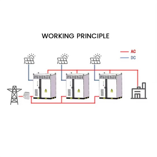
As the photovoltaic (PV) industry continues to evolve, advancements in Schematic diagram of inductive solar container inverter have become critical to optimizing the utilization of renewable energy sources. From innovative battery technologies to intelligent energy management systems, these solutions are transforming the way we store and distribute solar-generated electricity.
6 FAQs about [Schematic diagram of inductive solar container inverter]
What is a solar inverter circuit diagram PDF?A solar inverter circuit diagram pdf provides an easy-to-understand representation of how a solar inverter works. This diagram shows all the individual components of the inverter and their connections. It also contains information about the type of materials used and the amount of power that can be generated with different types of solar panels.
How many stages are there in a solar inverter circuit?13. There are five stages of this Circuit: This PV Solar Inverter Circuit uses a 12-volt/20-watt solar panel to obtain input bias. When exposed to the open Sun, the solar panel produces a peak output of 12 volts at 1600 mA.
How to build a solar inverter?To easily understand the construction of a solar inverter lets discuss the following construction sample:- According to the circuit diagram initially do the assembling of the oscillator part which consist of the small components & IC. It is finely completed by interrelating the part leads itself and fusing the joints.
What are solar inverters?Solar inverters are also called as photovoltaic solar inverters. These devices can help you save lot of money. The small-scale grid one have just two components i.e. the panels and inverter while the off grid systems are complicated and consists of batteries which allows users to use appliances during the night when there is no Sunlight available.
What are the output pins of an inverter circuit?Pins 13 and 11 give a complete oscillation output and a half oscillation at Pins 10 and Q, respectively. Each output pin provides a 50% duty cycle. This inverter circuit uses an IRF540 N Channel power Mosfet as a switching driver. It has high working temperature characteristics and provides quick switching.
How a solar inverter works?The solar panel and the batteries that are placed on rooftops attract Sun rays and then convert the Sunlight into electricity. The batteries too grab the extra electricity so that it can then be used to run appliances at night. Now after knowing what a solar inverter is, let’s talk about its working.
Related Contents
-
Bidirectional solar container inverter circuit schematic diagram
-
Solar container inverter electrical schematic diagram
-
Schematic diagram of heat dissipation and solar container inverter
-
Single-phase solar container inverter schematic diagram
-
Solar container inverter primary diagram
-
Schematic diagram of the solar container battery principle of integrated equipment
List of relevant information about Schematic diagram of inductive solar container inverter
PV Solar Inverter Circuit Diagram
IntroductionConstruction of CircuitWorking ExplanationApplication and UsesSolar power generation is widespread these days; therefore, when we think about solar energy, we picture panels arranged on a house''s roof. These panels convert Sun''s light into electricity, which is then sent to various devices throughout the home. It may seem simple, but it involves much more than just a few panels and cost-free electricity for t...circuits-diy suntechmall
DAY SOLAR INVERTER SCHEMATIC DIAGRAM OF
The China DAY solar inverter is a popular device for converting solar energy into usable electricity. Its schematic diagram shows key parts like components tracks
Grid Connected Inverter Reference Design (Rev. D)
Grid connected inverters (GCI) are commonly used in applications such as photovoltaic inverters to generate a regulated AC current to feed into the grid. The control design of this type of inverter may
Photovoltaic inverter output schematic diagram
ering the number of modul s in the system l part of the overall renewable energy scheme. In all solar inverters, the micro solar inverters are critical co In its simplest form, a transformerless inverter circuit
Inverter for the Solar Panel using an
The inverter can be powered by one solar panel with the 36 V DC nominal output voltage or by two solar panels connected in series each with the 18 V DC nominal output voltage. The inverter can also be
Inverter schematic diagram | Download Scientific Diagram
Download scientific diagram | Inverter schematic diagram from publication: A MICROCONTROLLER INVERTER FOR SOLAR HOME SYSTEMS | Southern Africa is endowed with abundant solar energy
The Essential Guide: 7 Wiring Diagrams for Power Inverter Installations
A power inverter schematic diagram is a visual representation of the electrical components and their connections within a power inverter. It provides a comprehensive overview of
Solar Inverters & Battery Energy Storage Systems (BESS)
Features Two inverter: Bi-directional inverter with battery and a solar inverter Offers higher flexibility. Easier installation, especially for retrofits. Get to keep grid-tied inverter Less efficient as the energy
Contact Integrated Localized Bess Provider
Enter your inquiry details, We will reply you in 24 hours.
A solar inverter circuit diagram pdf provides an easy-to-understand representation of how a solar inverter works. This diagram shows all the individual components of the inverter and their connections. It also contains information about the type of materials used and the amount of power that can be generated with different types of solar panels.
How many stages are there in a solar inverter circuit?13. There are five stages of this Circuit: This PV Solar Inverter Circuit uses a 12-volt/20-watt solar panel to obtain input bias. When exposed to the open Sun, the solar panel produces a peak output of 12 volts at 1600 mA.
How to build a solar inverter?To easily understand the construction of a solar inverter lets discuss the following construction sample:- According to the circuit diagram initially do the assembling of the oscillator part which consist of the small components & IC. It is finely completed by interrelating the part leads itself and fusing the joints.
What are solar inverters?Solar inverters are also called as photovoltaic solar inverters. These devices can help you save lot of money. The small-scale grid one have just two components i.e. the panels and inverter while the off grid systems are complicated and consists of batteries which allows users to use appliances during the night when there is no Sunlight available.
What are the output pins of an inverter circuit?Pins 13 and 11 give a complete oscillation output and a half oscillation at Pins 10 and Q, respectively. Each output pin provides a 50% duty cycle. This inverter circuit uses an IRF540 N Channel power Mosfet as a switching driver. It has high working temperature characteristics and provides quick switching.
How a solar inverter works?The solar panel and the batteries that are placed on rooftops attract Sun rays and then convert the Sunlight into electricity. The batteries too grab the extra electricity so that it can then be used to run appliances at night. Now after knowing what a solar inverter is, let’s talk about its working.
Related Contents
-
Bidirectional solar container inverter circuit schematic diagram
-
Solar container inverter electrical schematic diagram
-
Schematic diagram of heat dissipation and solar container inverter
-
Single-phase solar container inverter schematic diagram
-
Solar container inverter primary diagram
-
Schematic diagram of the solar container battery principle of integrated equipment
List of relevant information about Schematic diagram of inductive solar container inverter
PV Solar Inverter Circuit Diagram
IntroductionConstruction of CircuitWorking ExplanationApplication and UsesSolar power generation is widespread these days; therefore, when we think about solar energy, we picture panels arranged on a house''s roof. These panels convert Sun''s light into electricity, which is then sent to various devices throughout the home. It may seem simple, but it involves much more than just a few panels and cost-free electricity for t...circuits-diy suntechmall
DAY SOLAR INVERTER SCHEMATIC DIAGRAM OF
The China DAY solar inverter is a popular device for converting solar energy into usable electricity. Its schematic diagram shows key parts like components tracks
Grid Connected Inverter Reference Design (Rev. D)
Grid connected inverters (GCI) are commonly used in applications such as photovoltaic inverters to generate a regulated AC current to feed into the grid. The control design of this type of inverter may
Photovoltaic inverter output schematic diagram
ering the number of modul s in the system l part of the overall renewable energy scheme. In all solar inverters, the micro solar inverters are critical co In its simplest form, a transformerless inverter circuit
Inverter for the Solar Panel using an
The inverter can be powered by one solar panel with the 36 V DC nominal output voltage or by two solar panels connected in series each with the 18 V DC nominal output voltage. The inverter can also be
Inverter schematic diagram | Download Scientific Diagram
Download scientific diagram | Inverter schematic diagram from publication: A MICROCONTROLLER INVERTER FOR SOLAR HOME SYSTEMS | Southern Africa is endowed with abundant solar energy
The Essential Guide: 7 Wiring Diagrams for Power Inverter Installations
A power inverter schematic diagram is a visual representation of the electrical components and their connections within a power inverter. It provides a comprehensive overview of
Solar Inverters & Battery Energy Storage Systems (BESS)
Features Two inverter: Bi-directional inverter with battery and a solar inverter Offers higher flexibility. Easier installation, especially for retrofits. Get to keep grid-tied inverter Less efficient as the energy
Contact Integrated Localized Bess Provider
Enter your inquiry details, We will reply you in 24 hours.
13. There are five stages of this Circuit: This PV Solar Inverter Circuit uses a 12-volt/20-watt solar panel to obtain input bias. When exposed to the open Sun, the solar panel produces a peak output of 12 volts at 1600 mA.
How to build a solar inverter?To easily understand the construction of a solar inverter lets discuss the following construction sample:- According to the circuit diagram initially do the assembling of the oscillator part which consist of the small components & IC. It is finely completed by interrelating the part leads itself and fusing the joints.
What are solar inverters?Solar inverters are also called as photovoltaic solar inverters. These devices can help you save lot of money. The small-scale grid one have just two components i.e. the panels and inverter while the off grid systems are complicated and consists of batteries which allows users to use appliances during the night when there is no Sunlight available.
What are the output pins of an inverter circuit?Pins 13 and 11 give a complete oscillation output and a half oscillation at Pins 10 and Q, respectively. Each output pin provides a 50% duty cycle. This inverter circuit uses an IRF540 N Channel power Mosfet as a switching driver. It has high working temperature characteristics and provides quick switching.
How a solar inverter works?The solar panel and the batteries that are placed on rooftops attract Sun rays and then convert the Sunlight into electricity. The batteries too grab the extra electricity so that it can then be used to run appliances at night. Now after knowing what a solar inverter is, let’s talk about its working.
Related Contents
-
Bidirectional solar container inverter circuit schematic diagram
-
Solar container inverter electrical schematic diagram
-
Schematic diagram of heat dissipation and solar container inverter
-
Single-phase solar container inverter schematic diagram
-
Solar container inverter primary diagram
-
Schematic diagram of the solar container battery principle of integrated equipment
List of relevant information about Schematic diagram of inductive solar container inverter
PV Solar Inverter Circuit Diagram
IntroductionConstruction of CircuitWorking ExplanationApplication and UsesSolar power generation is widespread these days; therefore, when we think about solar energy, we picture panels arranged on a house''s roof. These panels convert Sun''s light into electricity, which is then sent to various devices throughout the home. It may seem simple, but it involves much more than just a few panels and cost-free electricity for t...circuits-diy suntechmall
DAY SOLAR INVERTER SCHEMATIC DIAGRAM OF
The China DAY solar inverter is a popular device for converting solar energy into usable electricity. Its schematic diagram shows key parts like components tracks
Grid Connected Inverter Reference Design (Rev. D)
Grid connected inverters (GCI) are commonly used in applications such as photovoltaic inverters to generate a regulated AC current to feed into the grid. The control design of this type of inverter may
Photovoltaic inverter output schematic diagram
ering the number of modul s in the system l part of the overall renewable energy scheme. In all solar inverters, the micro solar inverters are critical co In its simplest form, a transformerless inverter circuit
Inverter for the Solar Panel using an
The inverter can be powered by one solar panel with the 36 V DC nominal output voltage or by two solar panels connected in series each with the 18 V DC nominal output voltage. The inverter can also be
Inverter schematic diagram | Download Scientific Diagram
Download scientific diagram | Inverter schematic diagram from publication: A MICROCONTROLLER INVERTER FOR SOLAR HOME SYSTEMS | Southern Africa is endowed with abundant solar energy
The Essential Guide: 7 Wiring Diagrams for Power Inverter Installations
A power inverter schematic diagram is a visual representation of the electrical components and their connections within a power inverter. It provides a comprehensive overview of
Solar Inverters & Battery Energy Storage Systems (BESS)
Features Two inverter: Bi-directional inverter with battery and a solar inverter Offers higher flexibility. Easier installation, especially for retrofits. Get to keep grid-tied inverter Less efficient as the energy
Contact Integrated Localized Bess Provider
Enter your inquiry details, We will reply you in 24 hours.
To easily understand the construction of a solar inverter lets discuss the following construction sample:- According to the circuit diagram initially do the assembling of the oscillator part which consist of the small components & IC. It is finely completed by interrelating the part leads itself and fusing the joints.
What are solar inverters?Solar inverters are also called as photovoltaic solar inverters. These devices can help you save lot of money. The small-scale grid one have just two components i.e. the panels and inverter while the off grid systems are complicated and consists of batteries which allows users to use appliances during the night when there is no Sunlight available.
What are the output pins of an inverter circuit?Pins 13 and 11 give a complete oscillation output and a half oscillation at Pins 10 and Q, respectively. Each output pin provides a 50% duty cycle. This inverter circuit uses an IRF540 N Channel power Mosfet as a switching driver. It has high working temperature characteristics and provides quick switching.
How a solar inverter works?The solar panel and the batteries that are placed on rooftops attract Sun rays and then convert the Sunlight into electricity. The batteries too grab the extra electricity so that it can then be used to run appliances at night. Now after knowing what a solar inverter is, let’s talk about its working.
Related Contents
-
Bidirectional solar container inverter circuit schematic diagram
-
Solar container inverter electrical schematic diagram
-
Schematic diagram of heat dissipation and solar container inverter
-
Single-phase solar container inverter schematic diagram
-
Solar container inverter primary diagram
-
Schematic diagram of the solar container battery principle of integrated equipment
List of relevant information about Schematic diagram of inductive solar container inverter
PV Solar Inverter Circuit Diagram
IntroductionConstruction of CircuitWorking ExplanationApplication and UsesSolar power generation is widespread these days; therefore, when we think about solar energy, we picture panels arranged on a house''s roof. These panels convert Sun''s light into electricity, which is then sent to various devices throughout the home. It may seem simple, but it involves much more than just a few panels and cost-free electricity for t...circuits-diy suntechmall
DAY SOLAR INVERTER SCHEMATIC DIAGRAM OF
The China DAY solar inverter is a popular device for converting solar energy into usable electricity. Its schematic diagram shows key parts like components tracks
Grid Connected Inverter Reference Design (Rev. D)
Grid connected inverters (GCI) are commonly used in applications such as photovoltaic inverters to generate a regulated AC current to feed into the grid. The control design of this type of inverter may
Photovoltaic inverter output schematic diagram
ering the number of modul s in the system l part of the overall renewable energy scheme. In all solar inverters, the micro solar inverters are critical co In its simplest form, a transformerless inverter circuit
Inverter for the Solar Panel using an
The inverter can be powered by one solar panel with the 36 V DC nominal output voltage or by two solar panels connected in series each with the 18 V DC nominal output voltage. The inverter can also be
Inverter schematic diagram | Download Scientific Diagram
Download scientific diagram | Inverter schematic diagram from publication: A MICROCONTROLLER INVERTER FOR SOLAR HOME SYSTEMS | Southern Africa is endowed with abundant solar energy
The Essential Guide: 7 Wiring Diagrams for Power Inverter Installations
A power inverter schematic diagram is a visual representation of the electrical components and their connections within a power inverter. It provides a comprehensive overview of
Solar Inverters & Battery Energy Storage Systems (BESS)
Features Two inverter: Bi-directional inverter with battery and a solar inverter Offers higher flexibility. Easier installation, especially for retrofits. Get to keep grid-tied inverter Less efficient as the energy
Solar inverters are also called as photovoltaic solar inverters. These devices can help you save lot of money. The small-scale grid one have just two components i.e. the panels and inverter while the off grid systems are complicated and consists of batteries which allows users to use appliances during the night when there is no Sunlight available.
What are the output pins of an inverter circuit?Pins 13 and 11 give a complete oscillation output and a half oscillation at Pins 10 and Q, respectively. Each output pin provides a 50% duty cycle. This inverter circuit uses an IRF540 N Channel power Mosfet as a switching driver. It has high working temperature characteristics and provides quick switching.
How a solar inverter works?The solar panel and the batteries that are placed on rooftops attract Sun rays and then convert the Sunlight into electricity. The batteries too grab the extra electricity so that it can then be used to run appliances at night. Now after knowing what a solar inverter is, let’s talk about its working.
Related Contents
-
Bidirectional solar container inverter circuit schematic diagram
-
Solar container inverter electrical schematic diagram
-
Schematic diagram of heat dissipation and solar container inverter
-
Single-phase solar container inverter schematic diagram
-
Solar container inverter primary diagram
-
Schematic diagram of the solar container battery principle of integrated equipment
List of relevant information about Schematic diagram of inductive solar container inverter
PV Solar Inverter Circuit Diagram
IntroductionConstruction of CircuitWorking ExplanationApplication and UsesSolar power generation is widespread these days; therefore, when we think about solar energy, we picture panels arranged on a house''s roof. These panels convert Sun''s light into electricity, which is then sent to various devices throughout the home. It may seem simple, but it involves much more than just a few panels and cost-free electricity for t...circuits-diy suntechmall
DAY SOLAR INVERTER SCHEMATIC DIAGRAM OF
The China DAY solar inverter is a popular device for converting solar energy into usable electricity. Its schematic diagram shows key parts like components tracks
Grid Connected Inverter Reference Design (Rev. D)
Grid connected inverters (GCI) are commonly used in applications such as photovoltaic inverters to generate a regulated AC current to feed into the grid. The control design of this type of inverter may
Photovoltaic inverter output schematic diagram
ering the number of modul s in the system l part of the overall renewable energy scheme. In all solar inverters, the micro solar inverters are critical co In its simplest form, a transformerless inverter circuit
Inverter for the Solar Panel using an
The inverter can be powered by one solar panel with the 36 V DC nominal output voltage or by two solar panels connected in series each with the 18 V DC nominal output voltage. The inverter can also be
Inverter schematic diagram | Download Scientific Diagram
Download scientific diagram | Inverter schematic diagram from publication: A MICROCONTROLLER INVERTER FOR SOLAR HOME SYSTEMS | Southern Africa is endowed with abundant solar energy
The Essential Guide: 7 Wiring Diagrams for Power Inverter Installations
A power inverter schematic diagram is a visual representation of the electrical components and their connections within a power inverter. It provides a comprehensive overview of
Solar Inverters & Battery Energy Storage Systems (BESS)
Features Two inverter: Bi-directional inverter with battery and a solar inverter Offers higher flexibility. Easier installation, especially for retrofits. Get to keep grid-tied inverter Less efficient as the energy
Pins 13 and 11 give a complete oscillation output and a half oscillation at Pins 10 and Q, respectively. Each output pin provides a 50% duty cycle. This inverter circuit uses an IRF540 N Channel power Mosfet as a switching driver. It has high working temperature characteristics and provides quick switching.
How a solar inverter works?The solar panel and the batteries that are placed on rooftops attract Sun rays and then convert the Sunlight into electricity. The batteries too grab the extra electricity so that it can then be used to run appliances at night. Now after knowing what a solar inverter is, let’s talk about its working.
Related Contents
-
Bidirectional solar container inverter circuit schematic diagram
-
Solar container inverter electrical schematic diagram
-
Schematic diagram of heat dissipation and solar container inverter
-
Single-phase solar container inverter schematic diagram
-
Solar container inverter primary diagram
-
Schematic diagram of the solar container battery principle of integrated equipment
The solar panel and the batteries that are placed on rooftops attract Sun rays and then convert the Sunlight into electricity. The batteries too grab the extra electricity so that it can then be used to run appliances at night. Now after knowing what a solar inverter is, let’s talk about its working.
List of relevant information about Schematic diagram of inductive solar container inverter
PV Solar Inverter Circuit Diagram
IntroductionConstruction of CircuitWorking ExplanationApplication and UsesSolar power generation is widespread these days; therefore, when we think about solar energy, we picture panels arranged on a house''s roof. These panels convert Sun''s light into electricity, which is then sent to various devices throughout the home. It may seem simple, but it involves much more than just a few panels and cost-free electricity for t...circuits-diy suntechmall
DAY SOLAR INVERTER SCHEMATIC DIAGRAM OF
The China DAY solar inverter is a popular device for converting solar energy into usable electricity. Its schematic diagram shows key parts like components tracks
Grid Connected Inverter Reference Design (Rev. D)
Grid connected inverters (GCI) are commonly used in applications such as photovoltaic inverters to generate a regulated AC current to feed into the grid. The control design of this type of inverter may
Photovoltaic inverter output schematic diagram
ering the number of modul s in the system l part of the overall renewable energy scheme. In all solar inverters, the micro solar inverters are critical co In its simplest form, a transformerless inverter circuit
Inverter for the Solar Panel using an
The inverter can be powered by one solar panel with the 36 V DC nominal output voltage or by two solar panels connected in series each with the 18 V DC nominal output voltage. The inverter can also be
Inverter schematic diagram | Download Scientific Diagram
Download scientific diagram | Inverter schematic diagram from publication: A MICROCONTROLLER INVERTER FOR SOLAR HOME SYSTEMS | Southern Africa is endowed with abundant solar energy
The Essential Guide: 7 Wiring Diagrams for Power Inverter Installations
A power inverter schematic diagram is a visual representation of the electrical components and their connections within a power inverter. It provides a comprehensive overview of
Solar Inverters & Battery Energy Storage Systems (BESS)
Features Two inverter: Bi-directional inverter with battery and a solar inverter Offers higher flexibility. Easier installation, especially for retrofits. Get to keep grid-tied inverter Less efficient as the energy
Contact Integrated Localized Bess Provider
Enter your inquiry details, We will reply you in 24 hours.